This article is about a simple battery charger with indicator that shows if the battery is connected to the charger or not.
Figure 1: Battery Charger.
You can see this circuit working in this video:
Many years ago I purchased a battery charger from a homewares shop and the small LEDs would turn ON when the battery was placed in the charger. I was always thinking: "How do those chargers actually work?".
Step 1: Design the Circuit
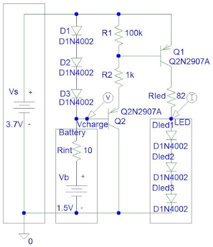
I have drawn the circuit in PSpice student edition version 9.1:
Figure 2: Circuit Design.
The 3.7 V is provided by the LM350K voltage regulator. I connected this voltage regulator to the 12 V battery. This voltage can give a maximum output current of 3 A that allows fast charging. During charging the voltage regulator was becoming hot. This is why I used a good heat sink.
Small electron current flows from the battery to the second transistor (Q2) and then to the first transistor (Q1) to turn ON the LED.
The R1 resistor ensures that the first transistor (Q1) OFF when the battery is disconnected. This is because the second transistor (Q2) is open circuit when the battery is disconnected and it is bad practice to leave circuit nodes disconnected.
The charging voltage is equal to:
Vcharge = Vs - 3*Vd
= 3.7 - 3*0.7 V
= 1.6 V
I considered tolerances of voltage regulator resistors to ensure that the charging voltage is above 1.5 V.
The LED current is equal to:
Iled = (Vs - Vsat - Vled) / Rled
= (3.7 V - 0.2 V - 2 V) / 82 ohms
= 18.2927 mA
I used big 20 mA LEDs. If you are using smaller LEDs then you need to adjust the Rled resistor so that it provides 10 mA (for typical LEDs) or 5 mA (for smallest LEDs).
The hardest part was calculating the resistors for the LM350K voltage regulator. Voltage regulator output is equal to:
Vo = 1.25*(1 + R2/R1) + (50*10^-6)*R2
(refer to the LM350K datasheets)
I created a Matlab file to try all the possibilities with E12 series resistors to find the most optimum combination. However, this combination is only for three resistors. If you use more resistors then you can find a more precise solution. However, precision is not that import for this particular application.
I used Octave software because it is free and provides similar basic functions to Matlab. The program gave me the following output:
R1 = 180 ohms
R2A = 330 ohms
Minimum Error = 0.14183
Preferred Voltage = 3.7 V
Output Voltage Without R2B = 3.5582 V
R2B = 22 ohms
Designed Voltage = 3.712 V
From the data we can figure out that:
R1 = 180 ohms
R2 = R2A + R2B = 330 ohms + 22 ohms = 352 ohms
This is why I used two resistors to implement R2.
The voltage regulator circuit is designed to provide 3.712 V. However, the voltage regulator output could be from 3.6 V to 3.8 V depending on the resistor tolerances. This is why I used Rled of 82 ohms instead of 68 ohms.
Step 2: Simulations
Simulation show a charging voltage of about 1.6 V and LED current of about 18 mA:
Step 3: Make the Circuit
I connected the resistors to transistors by twisting the pins and twisting the wires. I only used the soldering iron for the voltage regulator pins.
Figure 4: Make the Circuit.
Step 4: Testing
The circuit was not tested for batteries that have low charge.
Conclusion
Conclusion
It is important to mention that the Matlab program in the Appendix does not try all combinations with three resistors. It tries combination with only two resistors and determines the last resistor R3 from the subtraction reminder. Trying all combinations with three resistors would be more complicated.
The problem with using too many resistors to obtain a more precise voltage regulator output is that the tolerances add up.
Appendix (Matlab Code)
close all; clear all
E12=[100 120 150 180 220 270 330 390 470 560 680 820];
setvoltage=3.7;
for R1=1:length(E12)
for R2A=1:length(E12)
outvolt(R1,R2A)=1.25*(1+E12(R2A)/E12(R1))+(50*10^-6)*E12(R2A);
if (outvolt(R1,R2A)>setvoltage) % Output voltage must be below set voltage
err(R1,R2A)=1*10^9;
else
err(R1,R2A)=setvoltage-outvolt(R1,R2A);
end
disp(['R2A Index = ' num2str(R2A) ') R1 = ' num2str(E12(R1)) ...
' ohms, R2A = ' num2str(E12(R2A)) ' ohms, Output Voltage = ' ...
num2str(outvolt(R1,R2A)) 'V, Error = ' num2str(err(R1,R2A))])
end
[errorR2A(R1) errorR2Aindex(R1)]=min(err(R1,:));
disp(['R1 Index = ' num2str(R1) ') Minimum Error = ' num2str(errorR2A(R1)) ...
', Index = ' num2str(errorR2Aindex(R1))])
disp(' ')
end
[errorR1 errorR1index]=min(errorR2A);
SelectedR1=E12(errorR1index);
SelectedR2A=E12(errorR2Aindex(errorR1index));
disp(['R1 = ' num2str(SelectedR1) ' ohms']);
disp(['R2A = ' num2str(SelectedR2A) ' ohms']);
disp(['Minimum Error = ' num2str(err(errorR1index,errorR2Aindex(errorR1index)))]);
disp(['Preferred Voltage = ' num2str(setvoltage) ' V'])
disp(['Output Voltage Without R2B = ' ...
num2str(1.25*(1+SelectedR2A/SelectedR1)+(50*10^-6)*SelectedR2A) ' V'])
SelectedR2BCalc=((setvoltage-(50*10^-6)*SelectedR2A)/1.25-1)*SelectedR1-SelectedR2A;
E12small=[10 12 15 18 22 27 33 39 47 56 68 82];
for R2B=1:length(E12small)
errsmall(R2B)=abs(E12small(R2B)-SelectedR2BCalc);
end
[errorR2B errorR2Bindex]=min(errsmall);
SelectedR2B=E12small(errorR2Bindex);
disp(['R2B = ' num2str(SelectedR2B) ' ohms'])
DesignedVoltage=1.25*(1+(SelectedR2A+SelectedR2B)/SelectedR1)+ ...
(50*10^-6)*(SelectedR2A+SelectedR2B);
disp(['Designed Voltage = ' num2str(DesignedVoltage) ' V'])


No comments:
Post a Comment